
- All
- Product Name
- Product Keyword
- Product Model
- Product Summary
- Product Description
- Multi Field Search
 |


| Quantity: | |
|---|---|
WD-D63
Winston
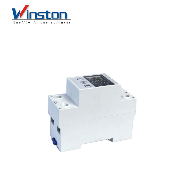
adjustable Intelligent digital Over and Under voltage limit current Protection device stabilizers with over voltage protector
voltage regulator stabilizer current protector
I. Application
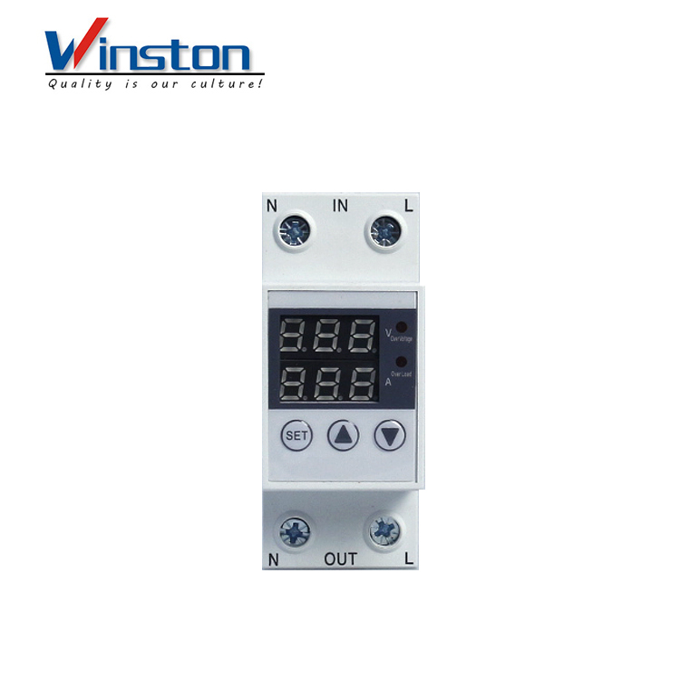
Intelligent over-/under-voltage limit current protector is a comprehensive intelligent protector thatintegrates over-current protection, over-voltage protection, under-voltage protection, voltagemeasurement, voltage display, current measurement and current display protection functions. In theevent of overcurrent fault or overvoltage fault or undervoltage fault, the protector can cut off thepower supply instantaneously and protect the electrical equipment from being burned out. When theline returns to normal, the protector can automatically restore power. The overcurrent value, overvoltage value, overvoltage recovery value, undervoltage value, undervoltage recovery value, operation time, recovery time and power-on time of the product can be set by themselves, as well asfault memory and fault inquiry functions and restore factory settings. The real-time voltage value andcurrent value are displayed cyclically. Each time you press the ∨ button, you can select the voltage orcurrent to be displayed separately. Press the ∧ button to resume the rotation display. It is e0asy to useand flexible, and can be used as a voltmeter or ammeter. Users can choose the appropriate categoryof protectors according to the actual situation.
II. Main technical parameters
Product model | WD-D63 |
Rated voltage | 230V50Hz |
Rated current | 1A ~ 63A (adjustable), 63A (default) |
Under-voltage protection value range | OFF-210V-150V (adjustable), 160V (default) |
Over-voltage protection value range | 221V-300V-OFF (adjustable), 280V (default) |
Recovery delay time | 2 ~ 512s (Default 60s) |
Delay time for power-on | 2 ~ 255s (Default 2s) |
Power consumption | ≤2W |
Electrical and mechanical lifespan | ≥40 thousand times |
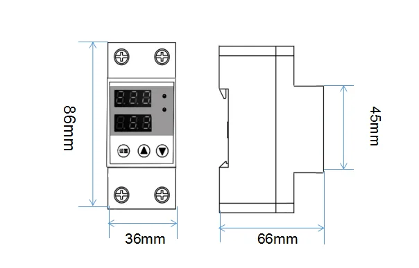
III.Product Dimensions
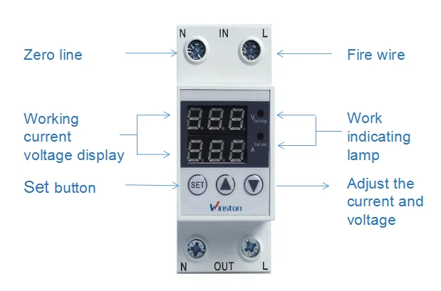
IV.Product introduction
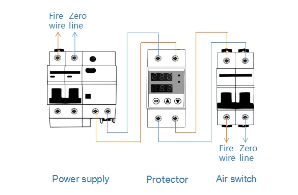
V.Product connection diagram
VI.Method of setting parameter
Under normal circumstances, press and hold “Set” for 3 seconds to enter the setting state. Theupper digital tube displays “P01” and the lower digital tube displays “280”. P01 means that the firstparameter set is the overvoltage value, "280" means the default overvoltage value is 280V. press ∧or ∨ key to modify the overvoltage value, modify the range 221V ~ 300V ~ OFF; press the set buttonagain, set Overvoltage recovery value, the above digital tube displays “P02”, the lower digital tubedisplays“250”, P02 indicates that the second parameter set is the overvoltage recovery value,“250”indicates the default overvoltage recovery value is 250V, press∧ Or ∨ key can modify theover-voltage recovery value, modify the range 220V ~ 300V ~ OFF, press the set button again, set theover-voltage protection action time, the above digital tube shows "P03", the lower digital tube shows"0.1". P03 means that the third parameter set is the overvoltage action time value, “0.1” means thedefault overvoltage action time is 0.1 second, press ∧or ∨ key to modify the overvoltage actiontime value, the modification range is 0.1~10 seconds; default value 0.1 second, it is recommended to≤ 0.1 seconds
Press “Settings” again, the above digital tube displays “P04”, and the lower digital tube displays “160”. P04 means that the fourth parameter set is the undervoltage value, "160" means the defaultundervoltage action value is 160V, press ∧ or ∨ key to modify the undervoltage action value, modifythe range OFF~150V~219V; press the set button again, Set the undervoltage recovery value. Theabove digital tube displays “P05”, the lower digital tube displays “180”, P05 indicates that the fifthparameter is the undervoltage recovery value, and “180” indicates the default undervoltage recoveryvalue is 180V. Press ∧ or ∨ key to modify the undervoltage recovery value. Modify the range fromOFF to 151V to 220V; Press the setup button again to set the undervoltage protection action time. Theupper digital tube displays “P06” and the lower digital tube displays “0.1”. P06 means that the sixthparameter set is the undervoltage action time value, “0.1” means the default overvoltage action timeis 0.1 second, press ∧ or ∨ key to modify the undervoltage action time value, the modification rangeis 0.1~30 seconds; default value 0.1 second, it is recommended to ≤ 0.5 seconds. Note: After the undervoltage operation time is set longer than 0.5 seconds, the relay cannot bedriven due to the power failure of the MCU. Therefore, when the setting time is longer than 0.5seconds, the grid cannot be disconnected when the power is cut off.
Press the set button again , set the current limit parameter.The upper digital tube displays “P07” andthe lower digital tube displays “63”. P07 means that the seventh parameter set is the overcurrentvalue, "63" means the default overcurrent protection value is 63A, press ∧ or ∨ key to modify theovercurrent protection value, modify the range 1A ~ 63A; press the set button again, set theovercurrent protection action time, the upper digital tube displays “P08”, and the lower digital tubedisplays “5.0”. P08 means that the eighth parameter set is the overcurrent action time value, "5.0" means the default overvoltage action time is 5.0 seconds, press ∧ or ∨ key to modify theovercurrent action time value, the modification range is 0.1~512 seconds; default value 5.0 seconds. Itis recommended depending on the usage.
Press "Settings" again to set the fault recovery delay time. The above digital tube displays “P09” andthe lower digital tube displays “60”. P09 indicates that the ninth parameter set is the fault recoverytime value, and “60” indicates that the default fault recovery time value is 60 seconds. Press ∧ or∨ to modify the fault recovery time value, and the modification range is 2 to 512 seconds.
Press "Settings" again to set the power-on time. The above digital tube displays “P10” and the lowerdigital tube displays “2”. P10 means that the tenth parameter set is the motor time value at power on, "2" means that the default power-on delay time value is 2 seconds, press ∧or ∨ key to modify thepower-on delay time value, modify the range 2~ 512 seconds.
Press the setup button again to set the reset mode selection. The upper digital tube displays “P11” and the lower digital tube displays “AU”. P11 means that the eleventh parameter set is the resetselection mode, "AU" means the default fault reset mode is automatic reset, press∧ key to modifythe fault reset mode to "HA" HA means manual reset, press ∧ key to select "AU" Switch toautomatic reset mode. When the manual reset mode HA is selected, the protector will not resumepower supply after the line fault is recovered. The protector can restore power only when the“Settings” button on the protector is manually pressed.
Press the “Settings” button again, the above digital tube displays “P12”, and the lower digital tubedisplays “1UL”. P12 indicates that the twelfth parameter set is the most recent fault of the fault query. “1UL” indicates that the last fault is an undervoltage fault, UL indicates undervoltage, UH indicatesovervoltage, and IH indicates overcurrent. For example, 1IH indicates the last time fault is anovercurrent fault. Press the ∧ key to query the last 5 faults.
Press "Settings" again, the above digital tube displays P13, and the lower digital tube displays theword "End". This setting is completed. Press the setting button again, the protector saves the data, exits the setting state and enters the running state. The above digital tube displays the current voltagevalue, and the lower digital tube displays the current current value of the line.
Note: After the user changes the parameters to “Settings”, be sure to follow the steps until “END” appears at the end and then press “Settings” to save the data, otherwise the modification will beinvalid.
After pressing “Setting”, if there is no operation within 10 seconds, the device status will beautomatically exited and the changed parameters will not be saved.
Restore factory settings: Press and hold the “∧” and “∨” buttons for 3 seconds at the sametime. The lower LED will be off and the factory default parameter value will be restored.
Voltage indicator: When the voltage is over voltage, the voltage indicator flashes rapidly. When thevoltage is under voltage, the voltage indicator flashes slowly. When the voltage is normal, the voltageindicator is always on.
Current indicator: When the current is over current, the current indicator flashes. When it isnormal, the current indicator is always on.
Warranty period mark: During the warranty period, the voltage indicator and current indicator arealways on. After the warranty period, the voltage indicator and current indicator are not lit duringnormal state. Only when there is abnormal voltage or over current, the voltage indicator or Thecurrent indicator flashes.
VII.Normal service conditions and installation environment
The ambient air temperature does not exceed +400C~-50C and the 24-hour average does not exceed+350C.
The relative humidity of the installation site does not exceed 50% when the ambient air temperatureis +400C; it can have a higher relative humidity at lower temperatures, for example, when the averageminimum temperature of the wettest month is +200C, the month The average maximum relativehumidity is up to 90%. Appropriate measures should be taken to prevent condensation due totemperature changes.
The altitude of the installation site should not exceed 2000m.
The protector shall be installed in a medium free of explosion hazard and there shall be no gas orconductive dust in the medium sufficient to corrode the metal and destroy the insulation.
VIII. Announcements
When performing various operations or tests, the user should follow the relevant procedures andpay attention to the following items to ensure correct and safe use.
According to the product identification input and output terminals are correctly wired.
The line conductors shall comply with the relevant current standard values and the load current shallnot exceed the maximum protection current value of the protector.
The neutral line N cannot be connected incorrectly and needs to be secure. The protector zero line Nis directly connected, and has no disconnection function.
Before turning on the power, please check the wiring carefully.
Do not touch live parts after the product is connected to the power supply to avoid electric shock.
This protector has no short-circuit protection function and needs to be used with a miniature circuitbreaker. If the miniature circuit breaker protection is not used, the short-circuit current cannot bebroken when there is a short-circuit fault at the input or output of the protector.
.Since the protector has a self-reset function, after the protector over-current is protected anddisconnected, the load electric appliance should be removed immediately, and the circuit line shouldbe checked. Otherwise, the protector will frequently turn on the load electrical appliance, andeventually the electrical appliance and the protector body will be damaged due to frequent switchingon and off for a long time.
This protector has no isolation function. Please use the miniature circuit breaker when using it, anddisconnect the front-end breaker switch when repairing the circuit line.
Please note! When the undervoltage breaking time is greater than 0.3 seconds, theprotector does not open after the power failure. (The power failure of the MCU doesnot work after 0.3 seconds of power failure)
After the overcurrent exceeds 5 times within the specified time, the protector lockwill not automatically restore the power supply. You must manually press the set buttonto unlock the power supply, which can effectively protect the device from frequendisconnection caused by not releasing the overcurrent in time.
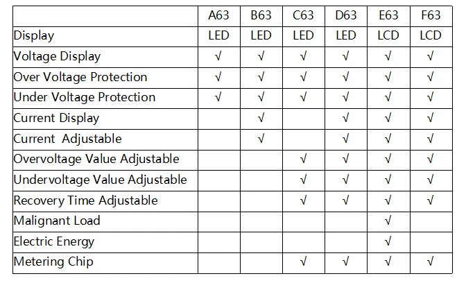
IX.Different between others
adjustable Intelligent digital Over and Under voltage limit current Protection device stabilizers with over voltage protector
voltage regulator stabilizer current protector
I. Application
Intelligent over-/under-voltage limit current protector is a comprehensive intelligent protector thatintegrates over-current protection, over-voltage protection, under-voltage protection, voltagemeasurement, voltage display, current measurement and current display protection functions. In theevent of overcurrent fault or overvoltage fault or undervoltage fault, the protector can cut off thepower supply instantaneously and protect the electrical equipment from being burned out. When theline returns to normal, the protector can automatically restore power. The overcurrent value, overvoltage value, overvoltage recovery value, undervoltage value, undervoltage recovery value, operation time, recovery time and power-on time of the product can be set by themselves, as well asfault memory and fault inquiry functions and restore factory settings. The real-time voltage value andcurrent value are displayed cyclically. Each time you press the ∨ button, you can select the voltage orcurrent to be displayed separately. Press the ∧ button to resume the rotation display. It is e0asy to useand flexible, and can be used as a voltmeter or ammeter. Users can choose the appropriate categoryof protectors according to the actual situation.
II. Main technical parameters
Product model | WD-D63 |
Rated voltage | 230V50Hz |
Rated current | 1A ~ 63A (adjustable), 63A (default) |
Under-voltage protection value range | OFF-210V-150V (adjustable), 160V (default) |
Over-voltage protection value range | 221V-300V-OFF (adjustable), 280V (default) |
Recovery delay time | 2 ~ 512s (Default 60s) |
Delay time for power-on | 2 ~ 255s (Default 2s) |
Power consumption | ≤2W |
Electrical and mechanical lifespan | ≥40 thousand times |
III.Product Dimensions
IV.Product introduction
V.Product connection diagram
VI.Method of setting parameter
Under normal circumstances, press and hold “Set” for 3 seconds to enter the setting state. Theupper digital tube displays “P01” and the lower digital tube displays “280”. P01 means that the firstparameter set is the overvoltage value, "280" means the default overvoltage value is 280V. press ∧or ∨ key to modify the overvoltage value, modify the range 221V ~ 300V ~ OFF; press the set buttonagain, set Overvoltage recovery value, the above digital tube displays “P02”, the lower digital tubedisplays“250”, P02 indicates that the second parameter set is the overvoltage recovery value,“250”indicates the default overvoltage recovery value is 250V, press∧ Or ∨ key can modify theover-voltage recovery value, modify the range 220V ~ 300V ~ OFF, press the set button again, set theover-voltage protection action time, the above digital tube shows "P03", the lower digital tube shows"0.1". P03 means that the third parameter set is the overvoltage action time value, “0.1” means thedefault overvoltage action time is 0.1 second, press ∧or ∨ key to modify the overvoltage actiontime value, the modification range is 0.1~10 seconds; default value 0.1 second, it is recommended to≤ 0.1 seconds
Press “Settings” again, the above digital tube displays “P04”, and the lower digital tube displays “160”. P04 means that the fourth parameter set is the undervoltage value, "160" means the defaultundervoltage action value is 160V, press ∧ or ∨ key to modify the undervoltage action value, modifythe range OFF~150V~219V; press the set button again, Set the undervoltage recovery value. Theabove digital tube displays “P05”, the lower digital tube displays “180”, P05 indicates that the fifthparameter is the undervoltage recovery value, and “180” indicates the default undervoltage recoveryvalue is 180V. Press ∧ or ∨ key to modify the undervoltage recovery value. Modify the range fromOFF to 151V to 220V; Press the setup button again to set the undervoltage protection action time. Theupper digital tube displays “P06” and the lower digital tube displays “0.1”. P06 means that the sixthparameter set is the undervoltage action time value, “0.1” means the default overvoltage action timeis 0.1 second, press ∧ or ∨ key to modify the undervoltage action time value, the modification rangeis 0.1~30 seconds; default value 0.1 second, it is recommended to ≤ 0.5 seconds. Note: After the undervoltage operation time is set longer than 0.5 seconds, the relay cannot bedriven due to the power failure of the MCU. Therefore, when the setting time is longer than 0.5seconds, the grid cannot be disconnected when the power is cut off.
Press the set button again , set the current limit parameter.The upper digital tube displays “P07” andthe lower digital tube displays “63”. P07 means that the seventh parameter set is the overcurrentvalue, "63" means the default overcurrent protection value is 63A, press ∧ or ∨ key to modify theovercurrent protection value, modify the range 1A ~ 63A; press the set button again, set theovercurrent protection action time, the upper digital tube displays “P08”, and the lower digital tubedisplays “5.0”. P08 means that the eighth parameter set is the overcurrent action time value, "5.0" means the default overvoltage action time is 5.0 seconds, press ∧ or ∨ key to modify theovercurrent action time value, the modification range is 0.1~512 seconds; default value 5.0 seconds. Itis recommended depending on the usage.
Press "Settings" again to set the fault recovery delay time. The above digital tube displays “P09” andthe lower digital tube displays “60”. P09 indicates that the ninth parameter set is the fault recoverytime value, and “60” indicates that the default fault recovery time value is 60 seconds. Press ∧ or∨ to modify the fault recovery time value, and the modification range is 2 to 512 seconds.
Press "Settings" again to set the power-on time. The above digital tube displays “P10” and the lowerdigital tube displays “2”. P10 means that the tenth parameter set is the motor time value at power on, "2" means that the default power-on delay time value is 2 seconds, press ∧or ∨ key to modify thepower-on delay time value, modify the range 2~ 512 seconds.
Press the setup button again to set the reset mode selection. The upper digital tube displays “P11” and the lower digital tube displays “AU”. P11 means that the eleventh parameter set is the resetselection mode, "AU" means the default fault reset mode is automatic reset, press∧ key to modifythe fault reset mode to "HA" HA means manual reset, press ∧ key to select "AU" Switch toautomatic reset mode. When the manual reset mode HA is selected, the protector will not resumepower supply after the line fault is recovered. The protector can restore power only when the“Settings” button on the protector is manually pressed.
Press the “Settings” button again, the above digital tube displays “P12”, and the lower digital tubedisplays “1UL”. P12 indicates that the twelfth parameter set is the most recent fault of the fault query. “1UL” indicates that the last fault is an undervoltage fault, UL indicates undervoltage, UH indicatesovervoltage, and IH indicates overcurrent. For example, 1IH indicates the last time fault is anovercurrent fault. Press the ∧ key to query the last 5 faults.
Press "Settings" again, the above digital tube displays P13, and the lower digital tube displays theword "End". This setting is completed. Press the setting button again, the protector saves the data, exits the setting state and enters the running state. The above digital tube displays the current voltagevalue, and the lower digital tube displays the current current value of the line.
Note: After the user changes the parameters to “Settings”, be sure to follow the steps until “END” appears at the end and then press “Settings” to save the data, otherwise the modification will beinvalid.
After pressing “Setting”, if there is no operation within 10 seconds, the device status will beautomatically exited and the changed parameters will not be saved.
Restore factory settings: Press and hold the “∧” and “∨” buttons for 3 seconds at the sametime. The lower LED will be off and the factory default parameter value will be restored.
Voltage indicator: When the voltage is over voltage, the voltage indicator flashes rapidly. When thevoltage is under voltage, the voltage indicator flashes slowly. When the voltage is normal, the voltageindicator is always on.
Current indicator: When the current is over current, the current indicator flashes. When it isnormal, the current indicator is always on.
Warranty period mark: During the warranty period, the voltage indicator and current indicator arealways on. After the warranty period, the voltage indicator and current indicator are not lit duringnormal state. Only when there is abnormal voltage or over current, the voltage indicator or Thecurrent indicator flashes.
VII.Normal service conditions and installation environment
The ambient air temperature does not exceed +400C~-50C and the 24-hour average does not exceed+350C.
The relative humidity of the installation site does not exceed 50% when the ambient air temperatureis +400C; it can have a higher relative humidity at lower temperatures, for example, when the averageminimum temperature of the wettest month is +200C, the month The average maximum relativehumidity is up to 90%. Appropriate measures should be taken to prevent condensation due totemperature changes.
The altitude of the installation site should not exceed 2000m.
The protector shall be installed in a medium free of explosion hazard and there shall be no gas orconductive dust in the medium sufficient to corrode the metal and destroy the insulation.
VIII. Announcements
When performing various operations or tests, the user should follow the relevant procedures andpay attention to the following items to ensure correct and safe use.
According to the product identification input and output terminals are correctly wired.
The line conductors shall comply with the relevant current standard values and the load current shallnot exceed the maximum protection current value of the protector.
The neutral line N cannot be connected incorrectly and needs to be secure. The protector zero line Nis directly connected, and has no disconnection function.
Before turning on the power, please check the wiring carefully.
Do not touch live parts after the product is connected to the power supply to avoid electric shock.
This protector has no short-circuit protection function and needs to be used with a miniature circuitbreaker. If the miniature circuit breaker protection is not used, the short-circuit current cannot bebroken when there is a short-circuit fault at the input or output of the protector.
.Since the protector has a self-reset function, after the protector over-current is protected anddisconnected, the load electric appliance should be removed immediately, and the circuit line shouldbe checked. Otherwise, the protector will frequently turn on the load electrical appliance, andeventually the electrical appliance and the protector body will be damaged due to frequent switchingon and off for a long time.
This protector has no isolation function. Please use the miniature circuit breaker when using it, anddisconnect the front-end breaker switch when repairing the circuit line.
Please note! When the undervoltage breaking time is greater than 0.3 seconds, theprotector does not open after the power failure. (The power failure of the MCU doesnot work after 0.3 seconds of power failure)
After the overcurrent exceeds 5 times within the specified time, the protector lockwill not automatically restore the power supply. You must manually press the set buttonto unlock the power supply, which can effectively protect the device from frequendisconnection caused by not releasing the overcurrent in time.
IX.Different between others